Assembling guide
Consider from 2 up to 4 hours to achieve this build. You won’t need specific knowledge but some basic tools.
Toolkit
- hallen keys and socket wrench for 2.5, 3, 4 and 5mm bolts and nuts
- a nose plier
- wood glue
- tape
- a threader (for printed parts receiving screws)
- a multimeter to test the endstops (optional)
Tips & Conventions
- tape trick for retaining bolts and nuts
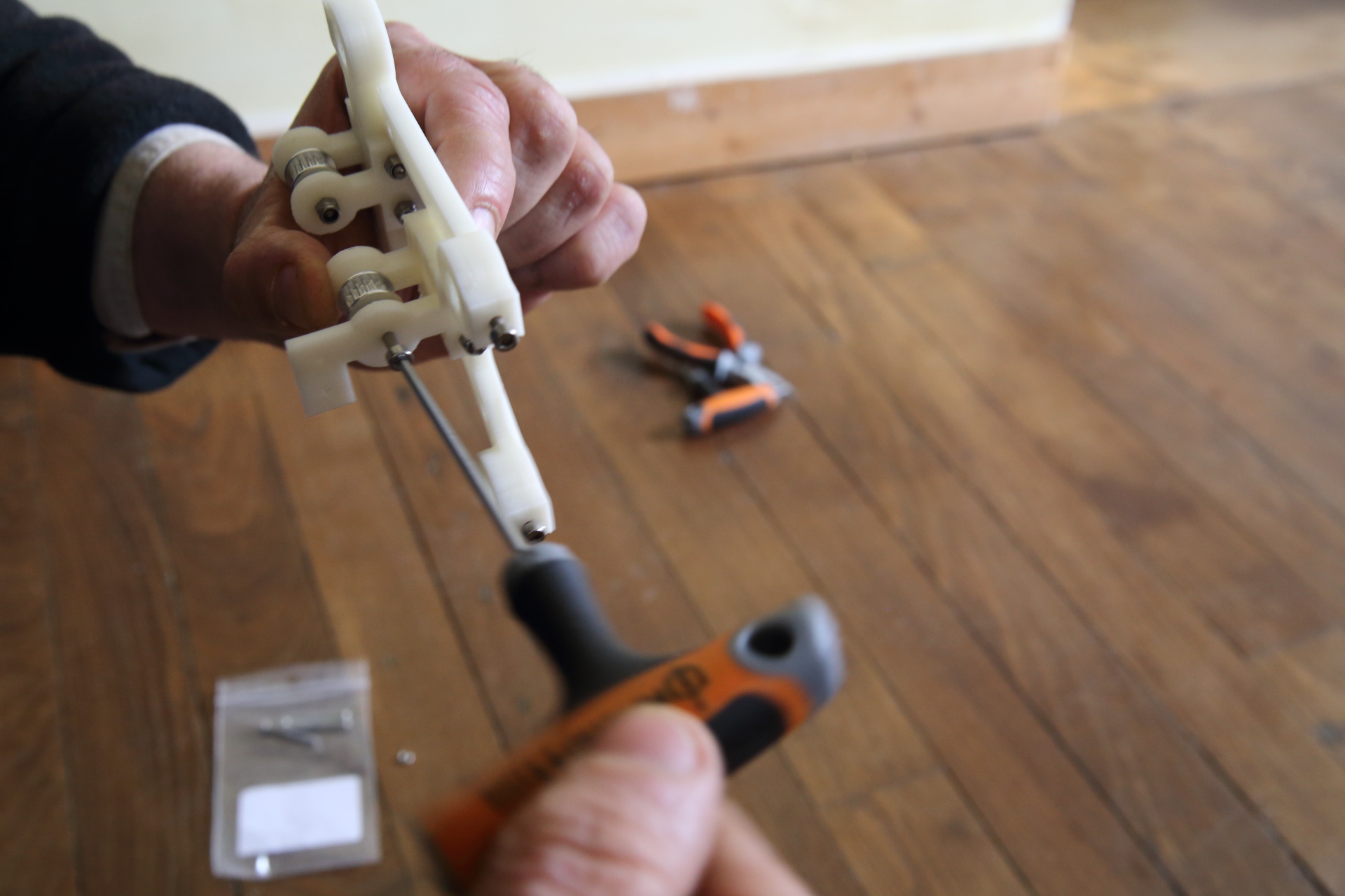
- using Hallen key to maintain screw while tightening
- « X axis » stands for the embossing head displacement
- « Y axis » is related to paper sheet movement
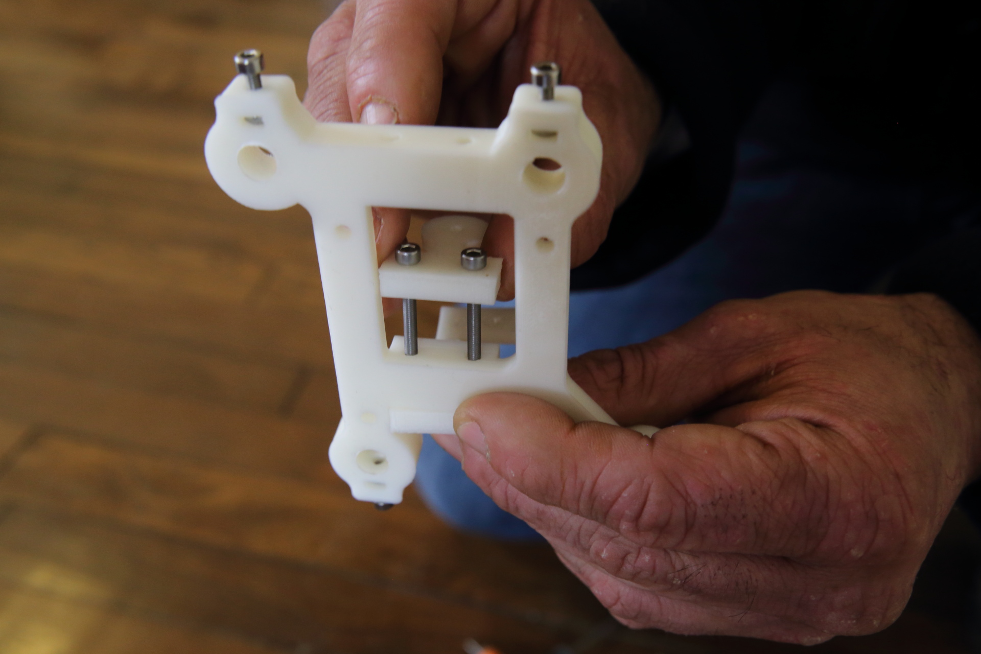
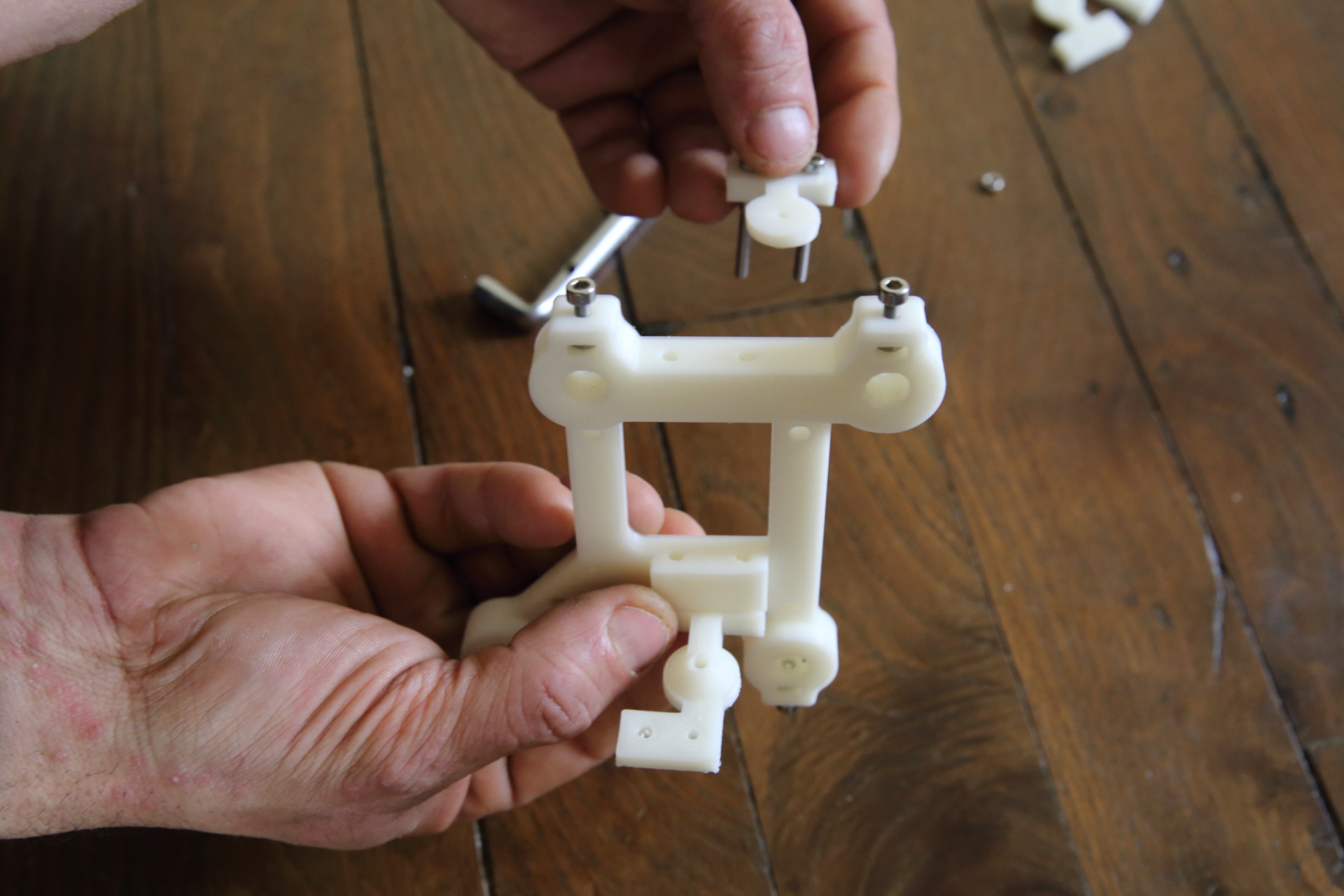
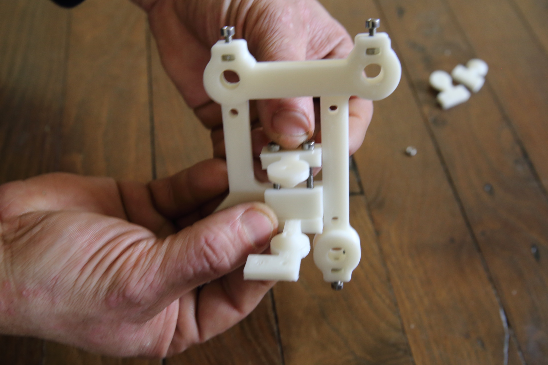
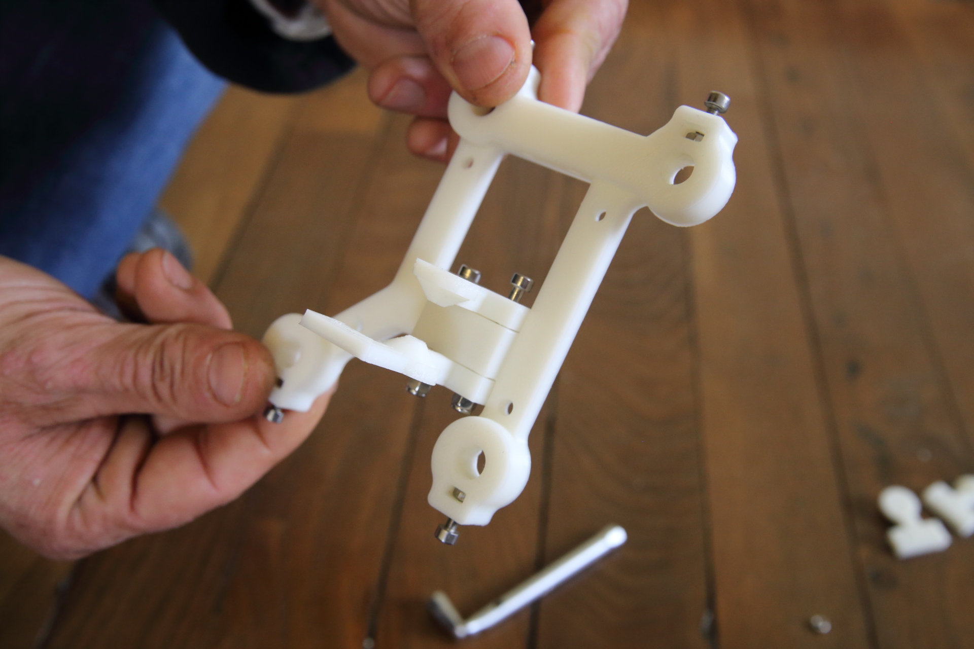
- X axis is assembly from two main parts. The female support is the top one while the male part of the embosser is at the bottom.
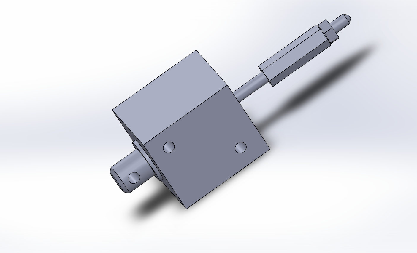
Machining the embossing « stylus »
The embossing tool is made of an M3 screw, machined with a dremel like tool. the tip of the tool need to be smooth (avoid sharp tip that will tear the embossed material)
Assemble the embossing tool
Screw the brace on the electro-magnet axle.
Screw embossing « stylus » in the brace.
lock the sylus with a counter lock nut.
Prepare top paper roll drive
We use epoxy glue to stick the sand paper on abs printed parts. Epoxy don’t stick on ABS so we prepare the parts with light sanding and cyanoacrilat glue. Be careful with cyanoacrilat glue, don’t stick your finger. Will start assembly with this part to let the glue gets dry.
Print 3 paper roll link to stl.
Laser cut some piece of 180 sand paper.
- Tap the screw hole with an M3 tap.
- Sand printed roll with sand Paper N°4 to scratch the printed surface where you want to stick sand paper.
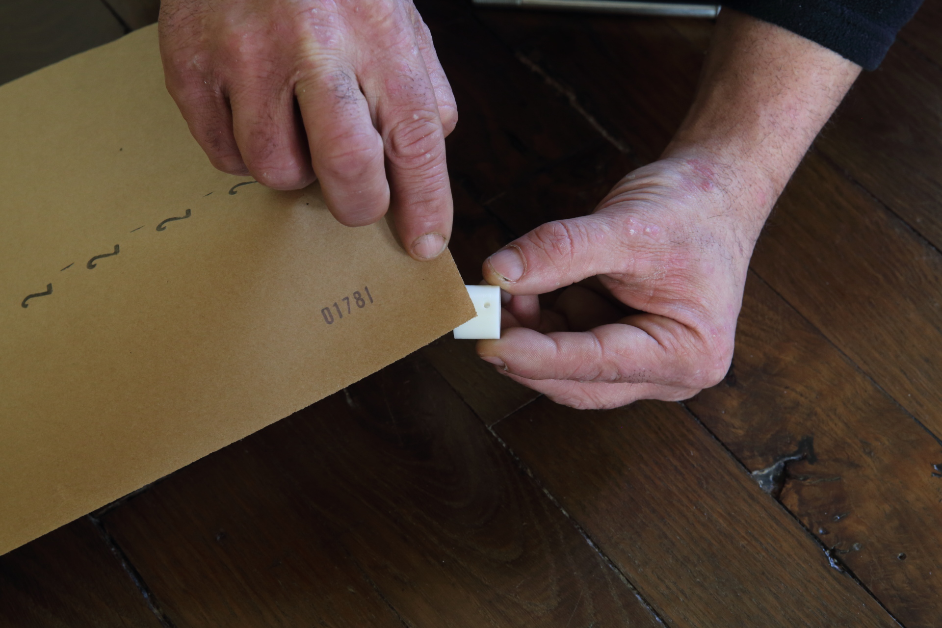
- « Paint » the printed parts with cyanoacrilat glue, let it dry.
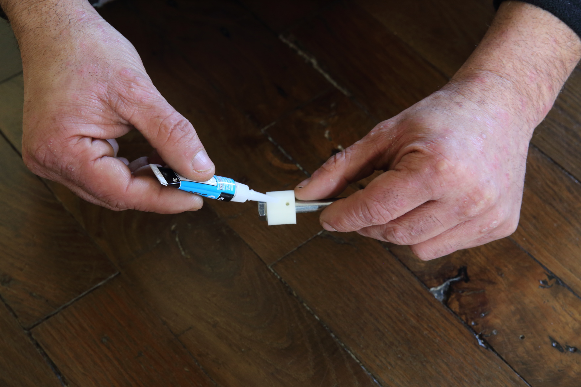
- Glue a piece of 180 sand paper on the part with bi-component epoxy glue.
- Fix the sand paper on roll with some rubber band. Let the roll dry for about 24h depending of the epoxy glue you’ve used (we used standard epoxy and let the roll dry for about 24 hours)
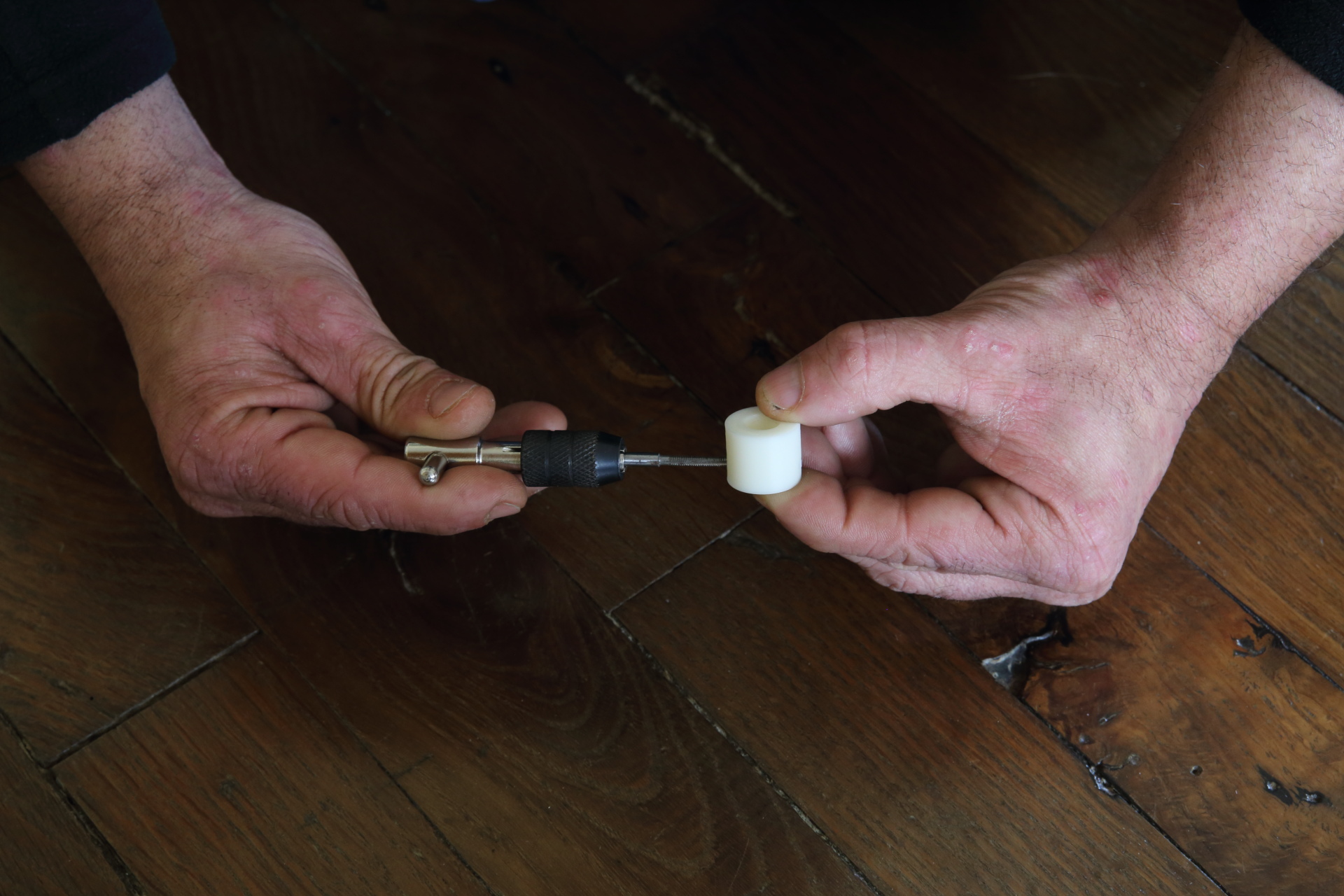
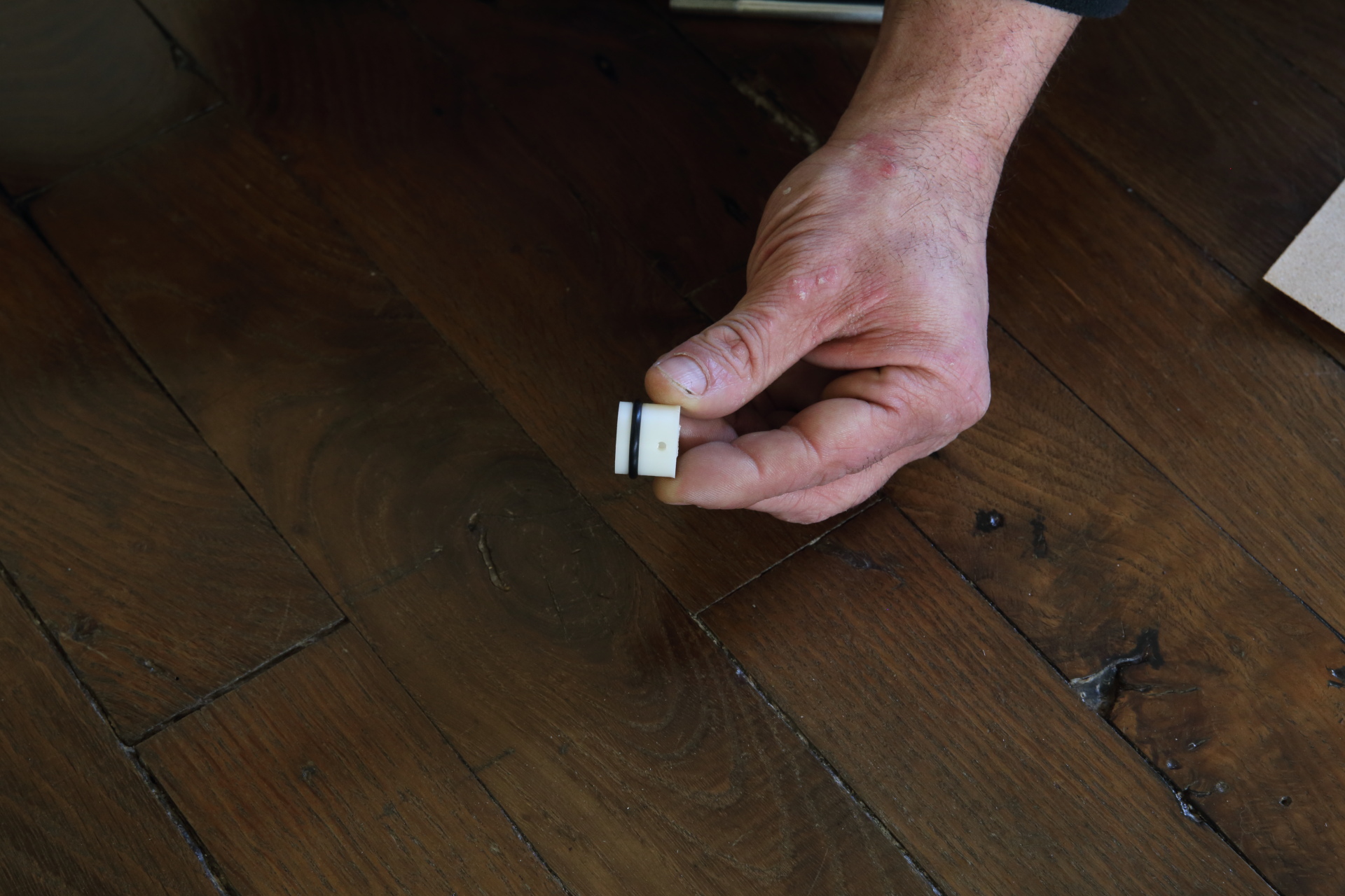
Prepare bottom paper roll drive
Print 3 paper roll link to stl.
- Tap the screw hole with an m3 tap.
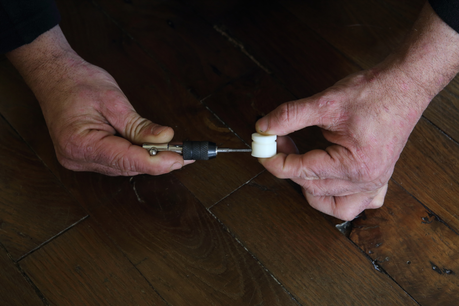
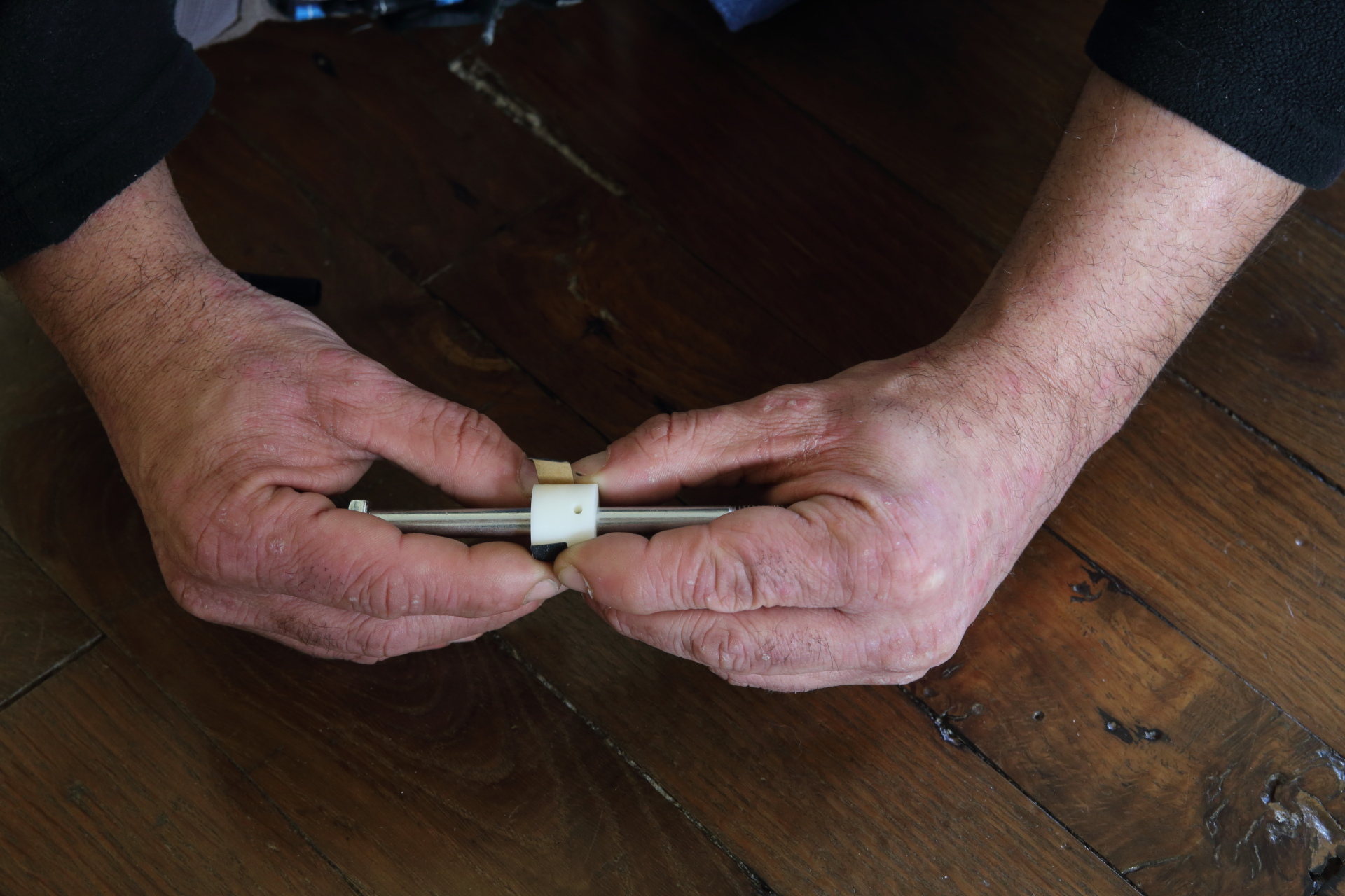
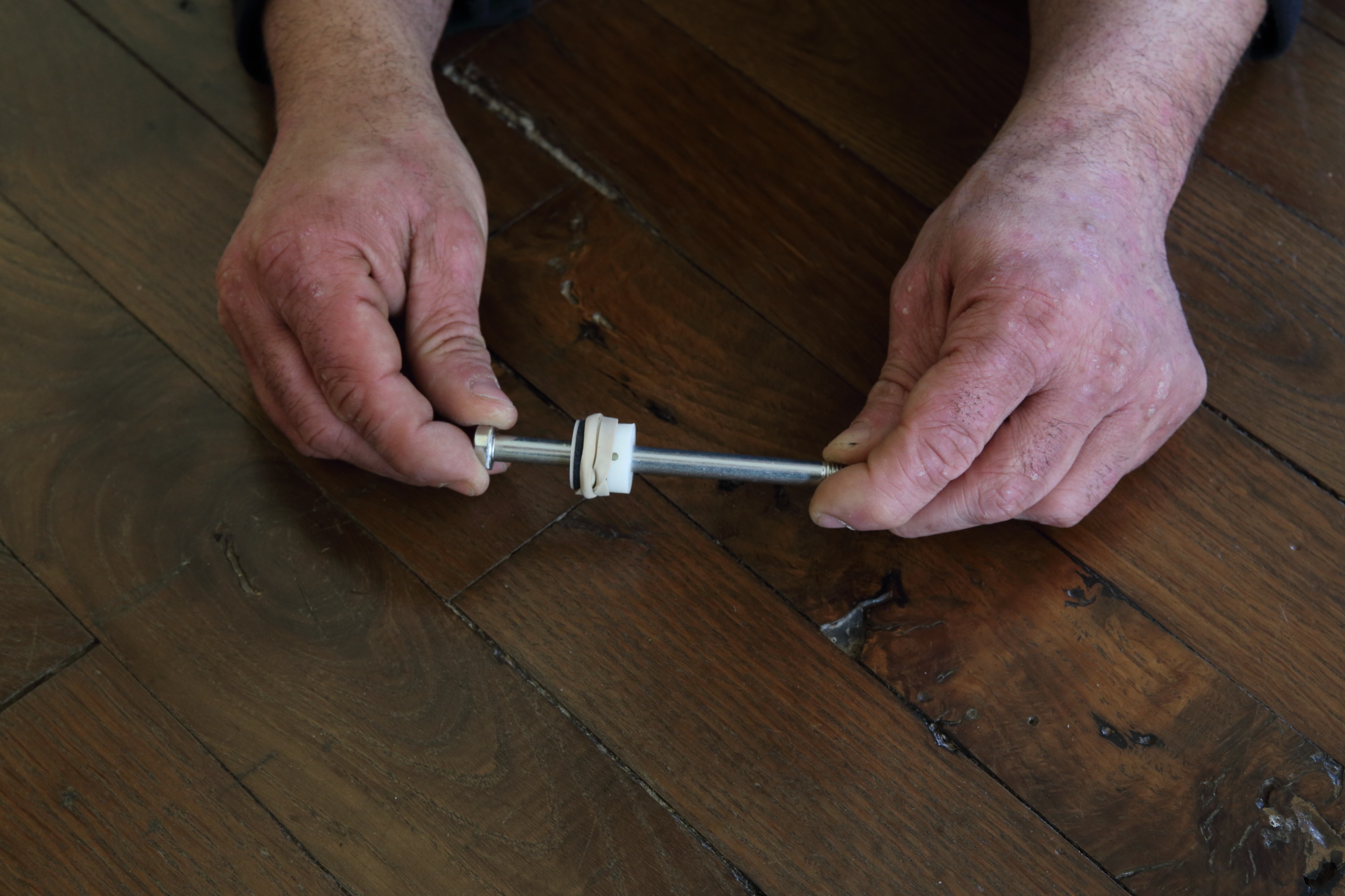
- Put an O-ring on the roll throat.
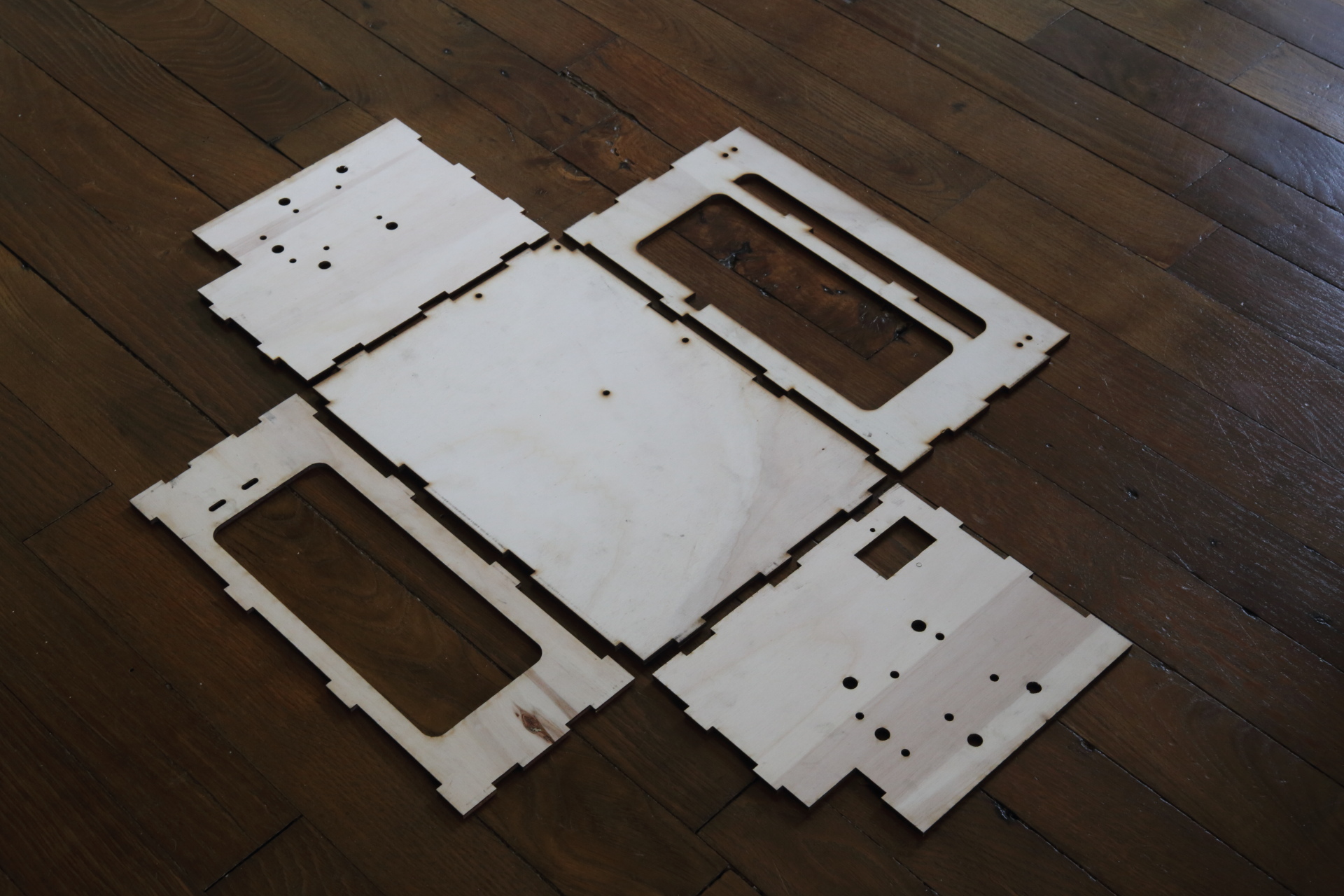
Laser cut the box
Material You will need 3 sheets of plywood 5mm thick , 600 mm x 400mm.
Use the dxf files in https://github.com/BrailleRapSP/BrailleRapSP/tree/master/lasercut to lasercut the 3 sheets.
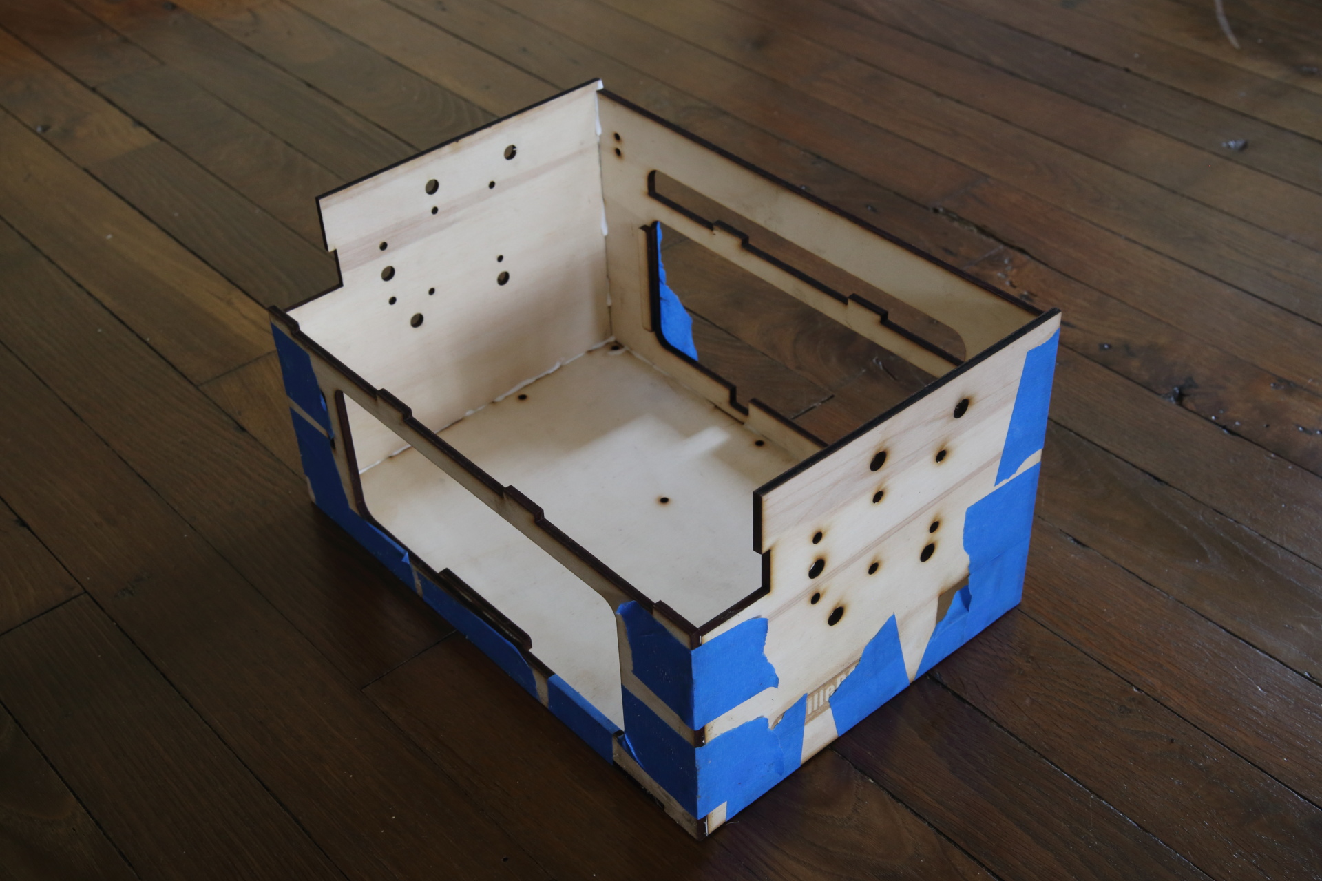
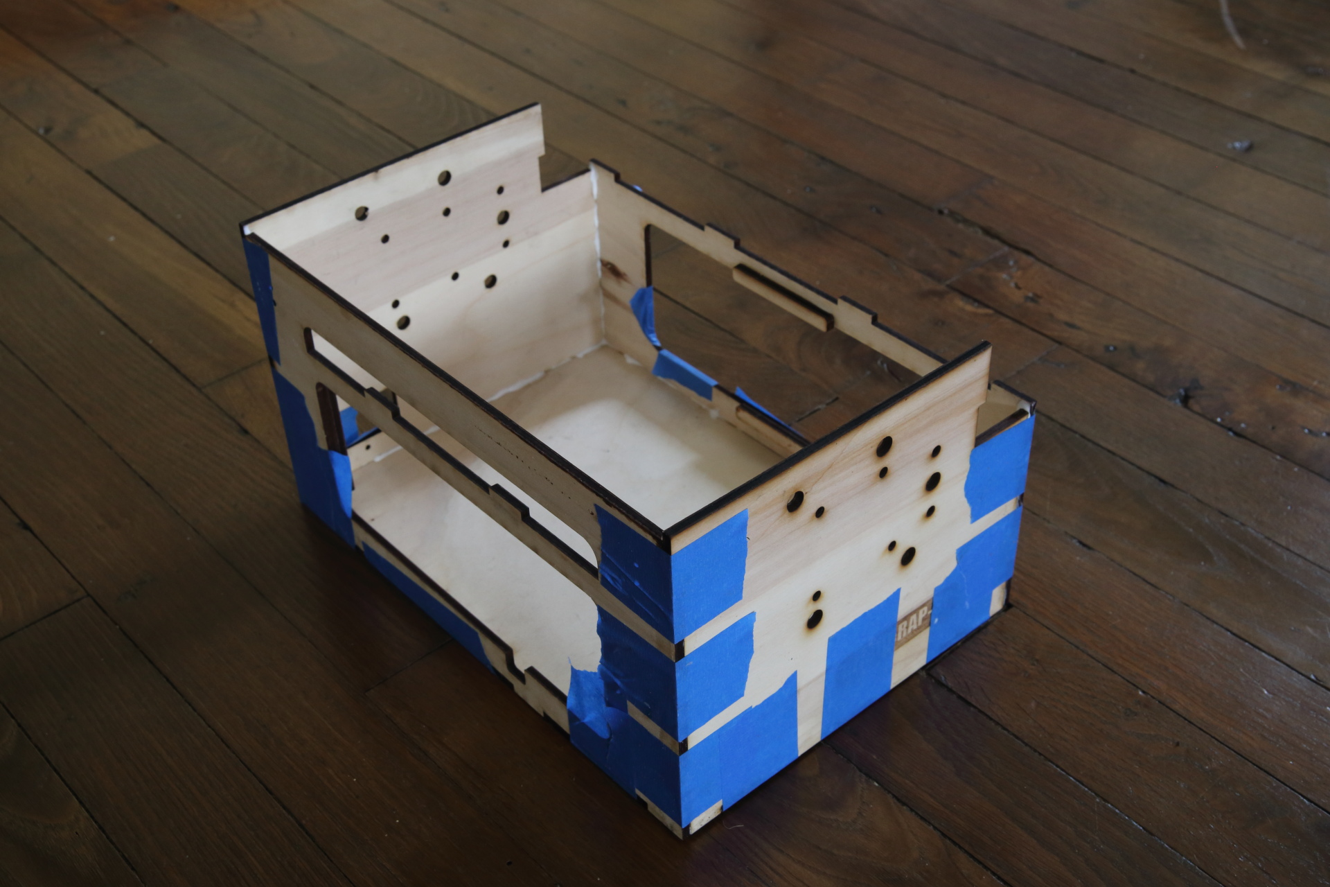
Assemble the box
- Depending on the lasercutter used, you may want to sand the cutted parts before starting assembly.
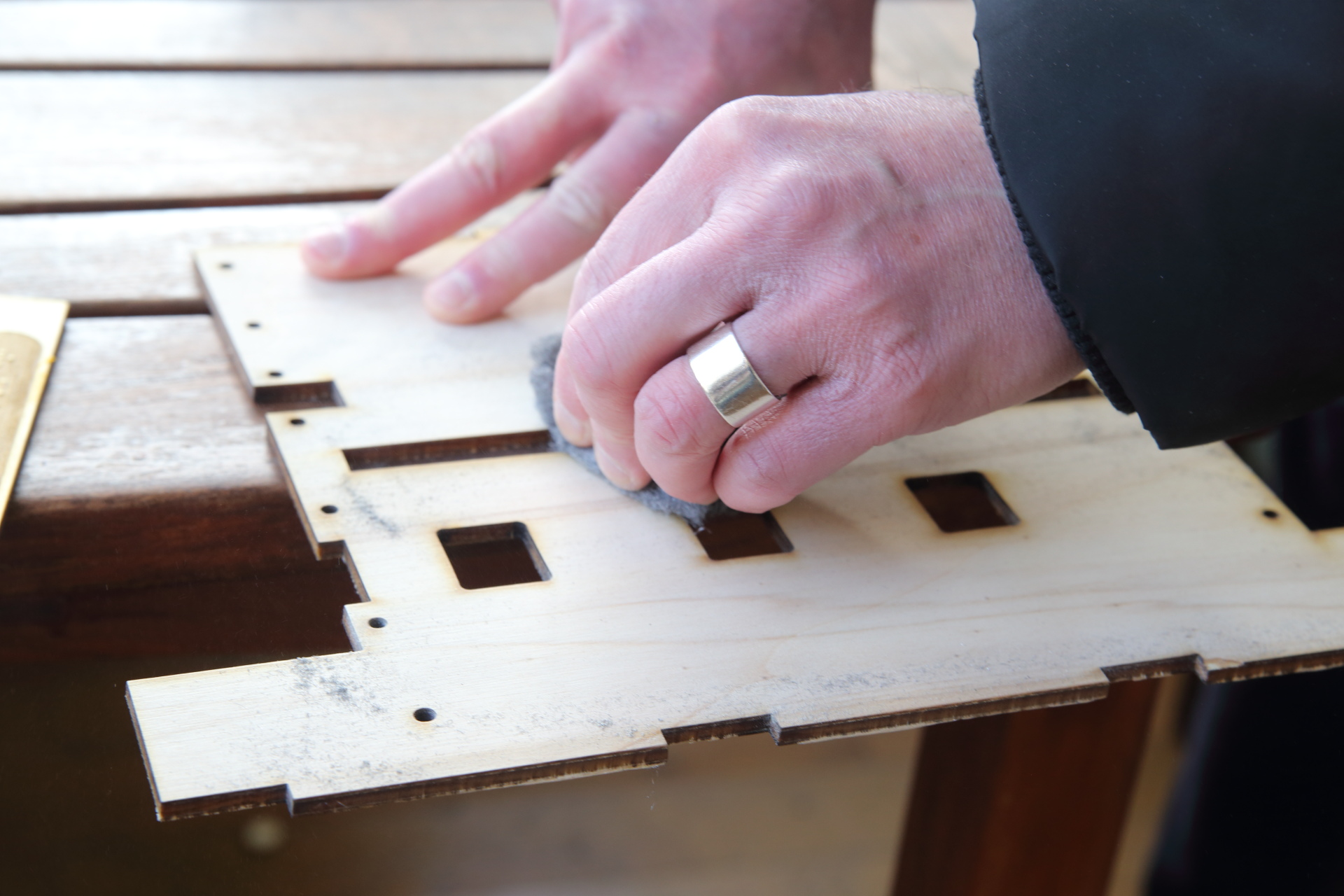
- Prepare the sides of the box on a flat surface.
- Start to glue left right and back sides of the box on the bottom side with wood glue,
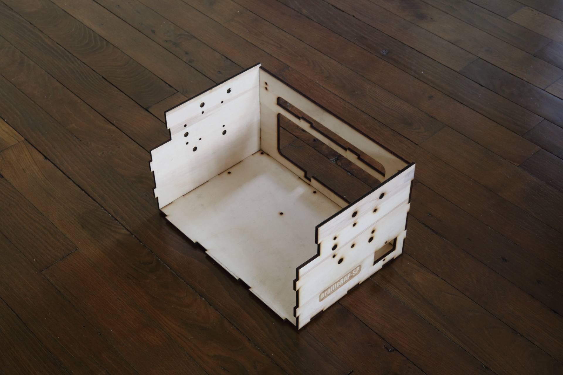
- then glue the front side.
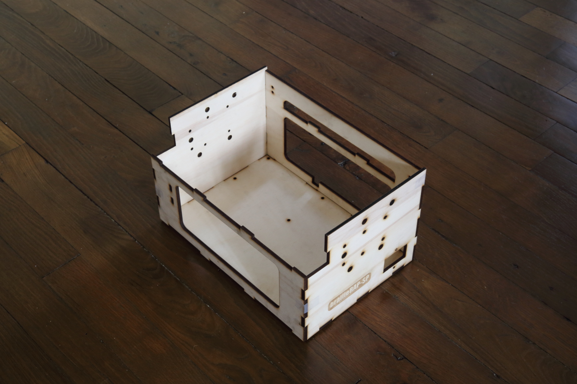
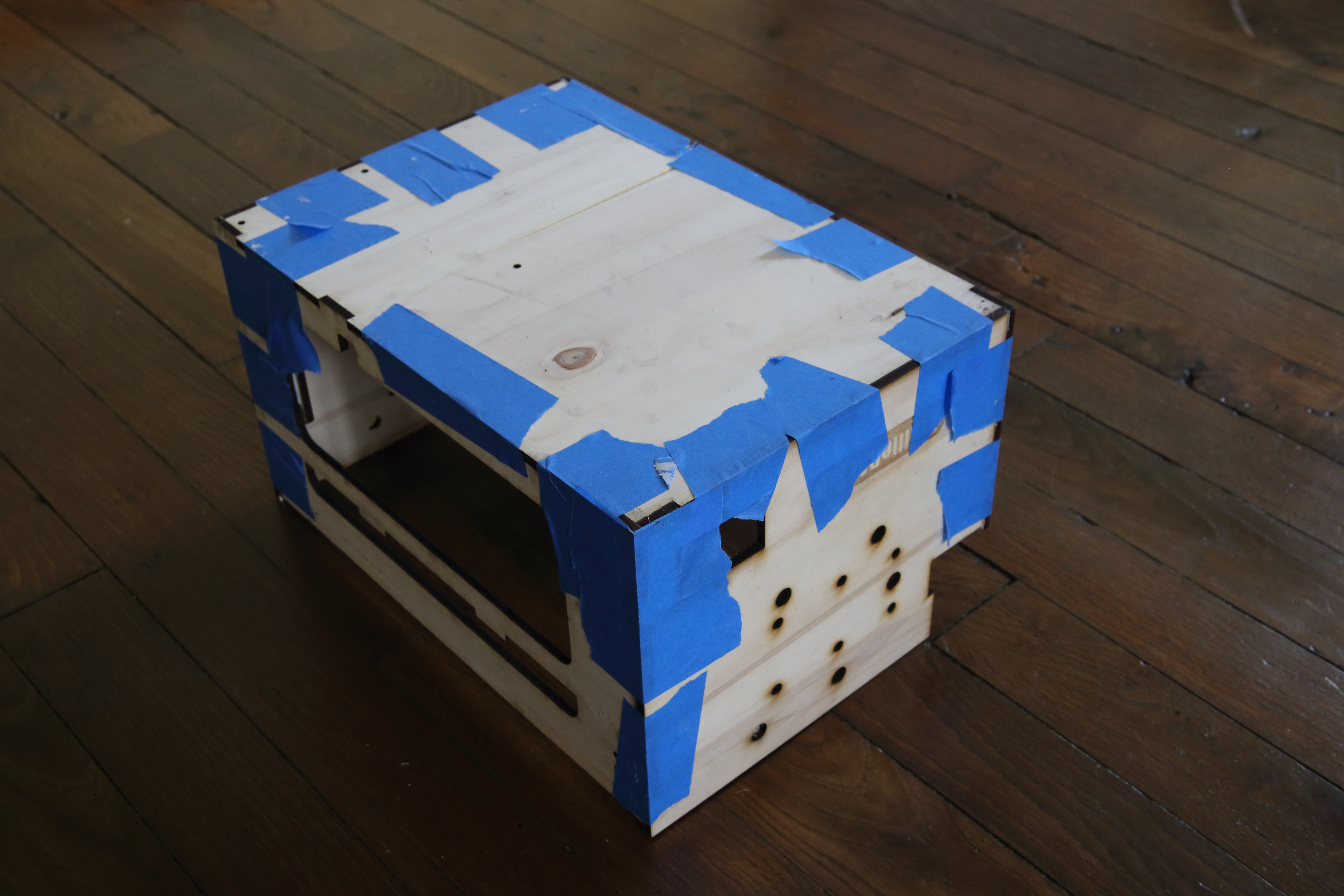
Assemble the 4 sides and the bottom, sticking them together with masking tape.
|
|
|
While the glue is drying (time depends on the glue you’ll use), let’s start assembling the right and left supports.
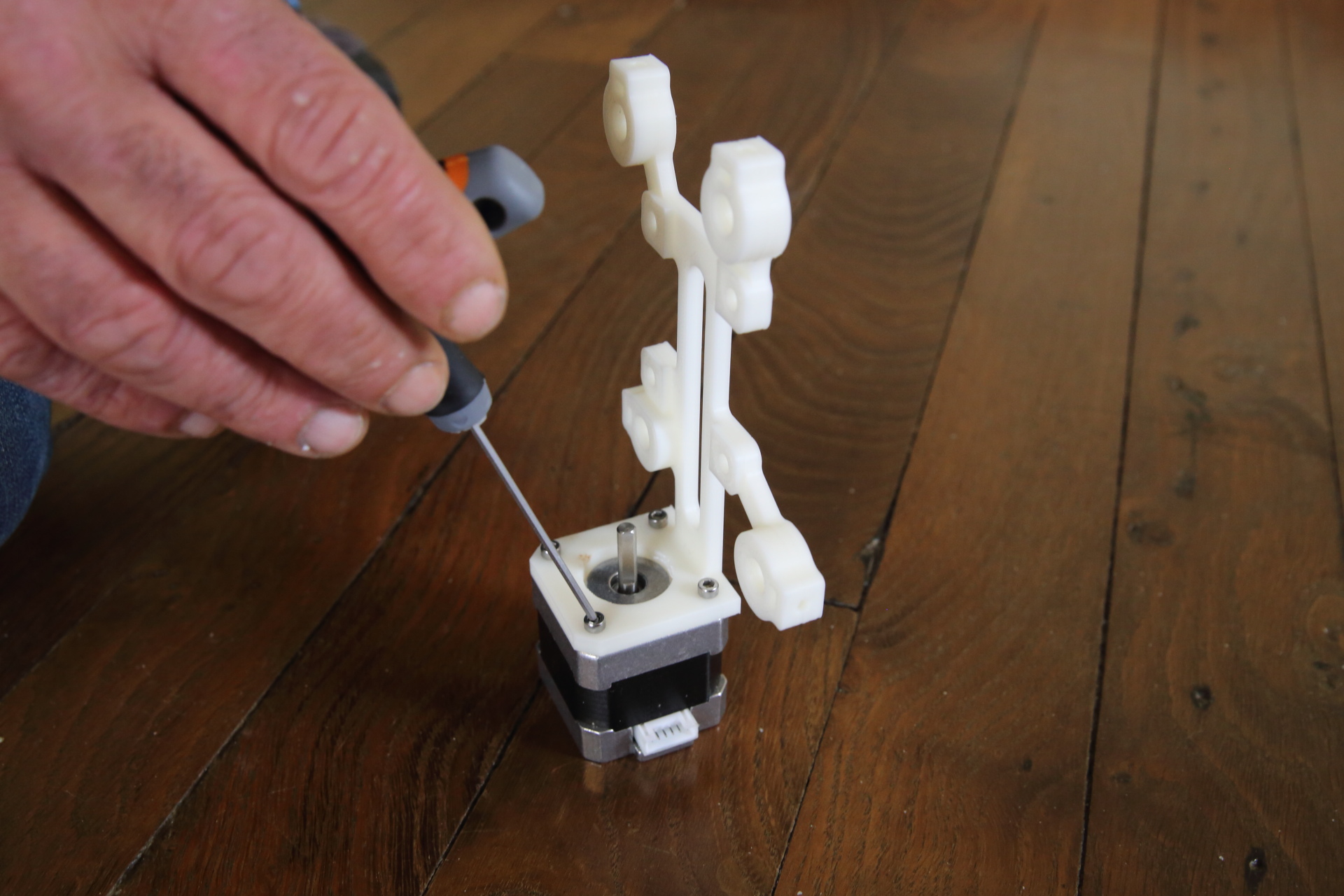
Right support assembly
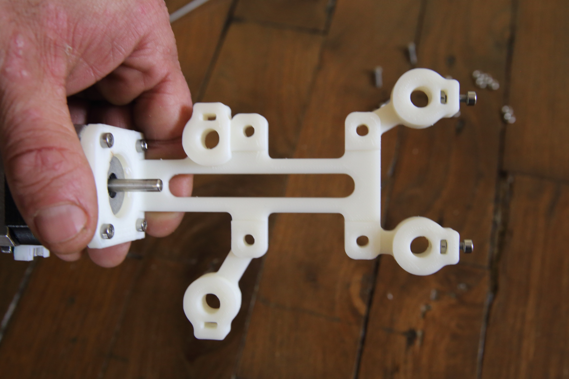
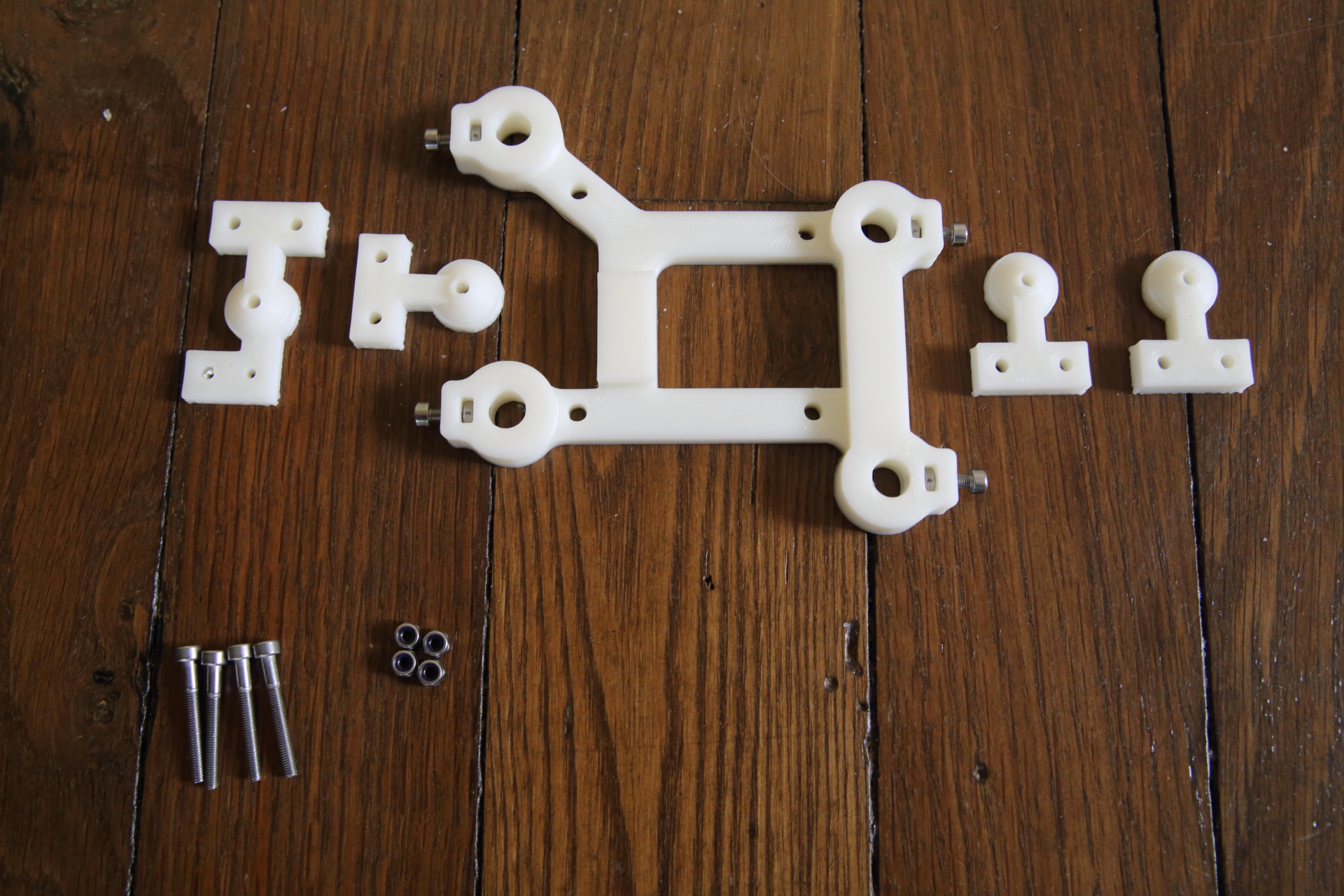
Attach the right_axes_mount.stl printed part to the X axis stepper’s motor.
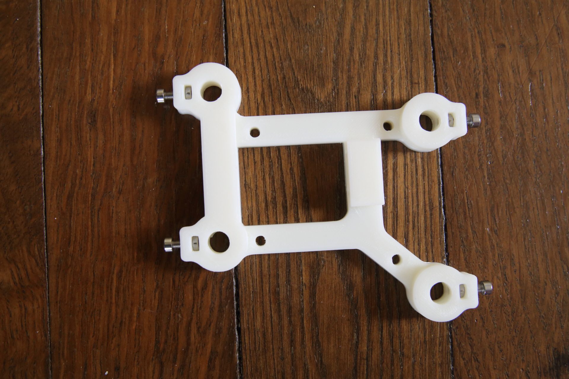
Insert M3 bolts into the right X axis support
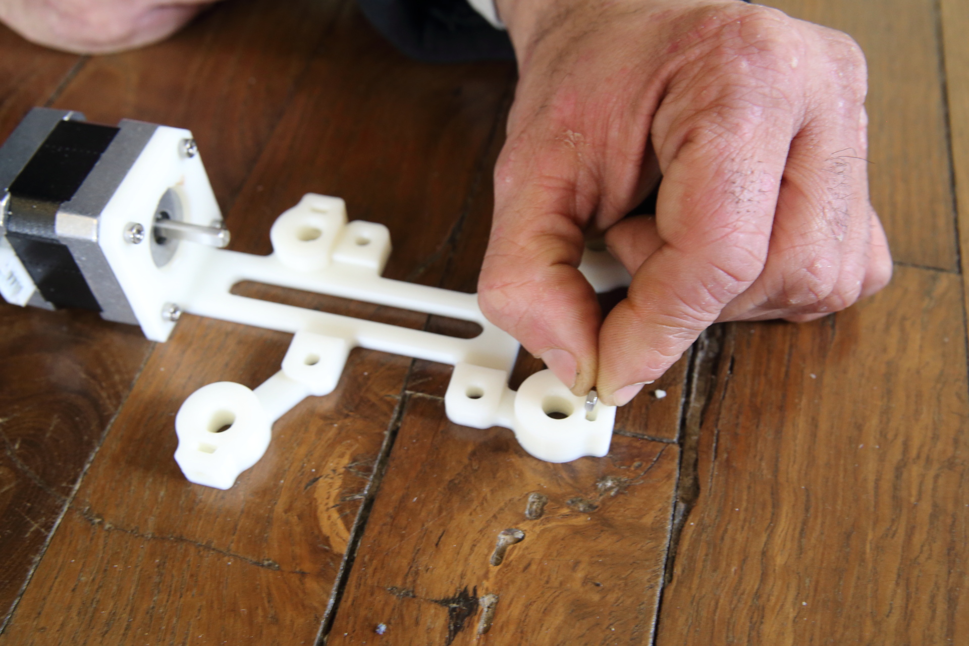
Add the BTR M3x14mm screws into the dedicated spaces. You should obtain this:
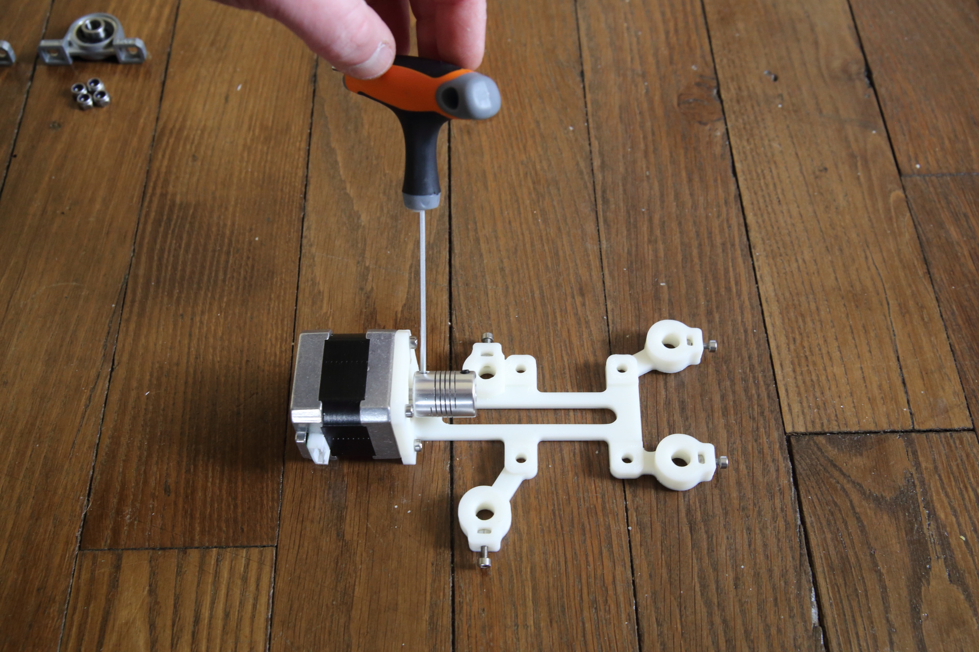
Add the coupler right onto the motor axis. Be sure to tight the screw correctly
Now it’s time to install the support into the right side of the wooden chassis, using 4 BTR M4 screws. You’ll add right after the KP08 according to the photo.
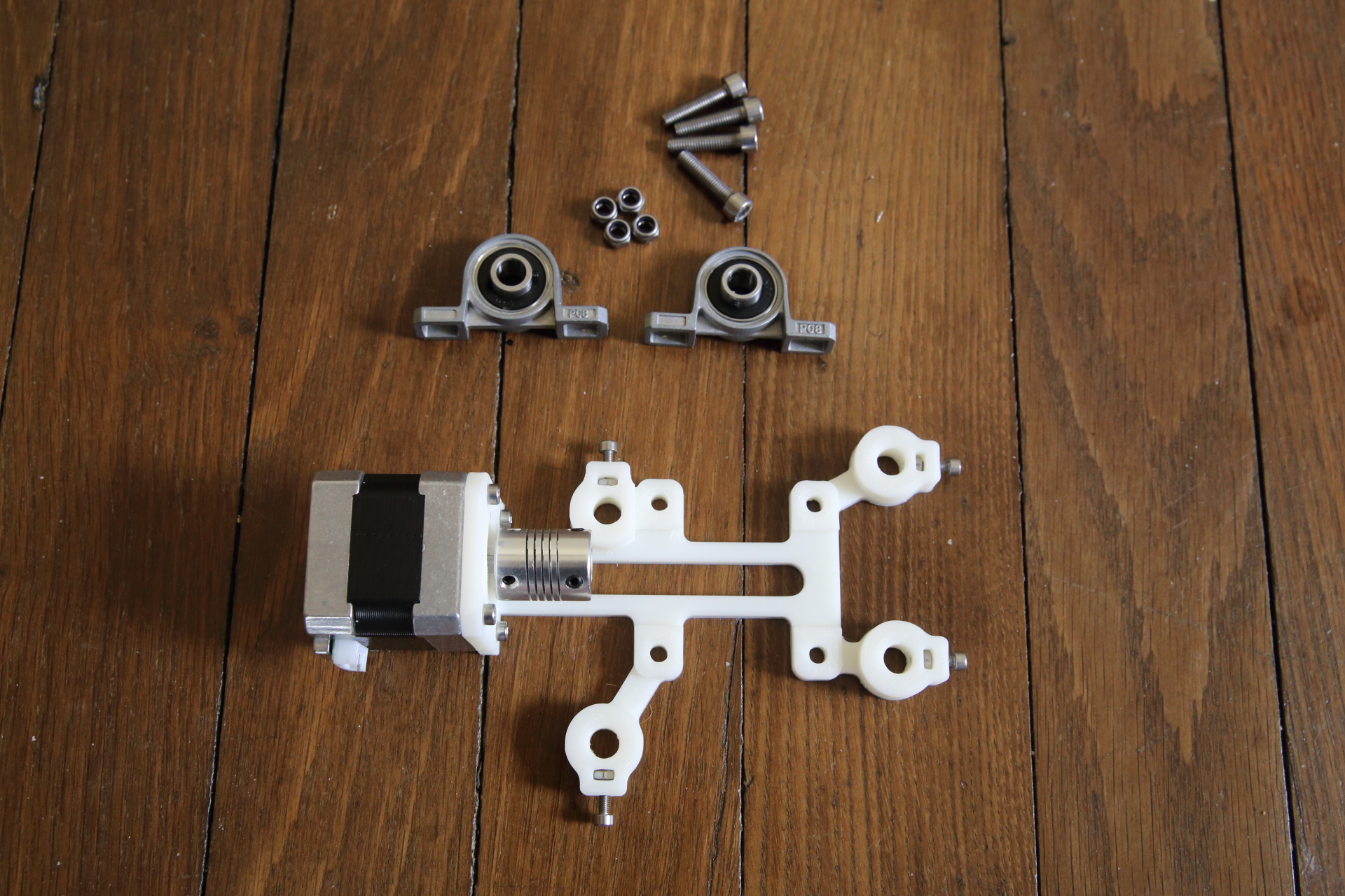
Be aware that KP08 parts are symetrically installed. The rings looking up for the upper part, facing down for the lower part. You should get this result:
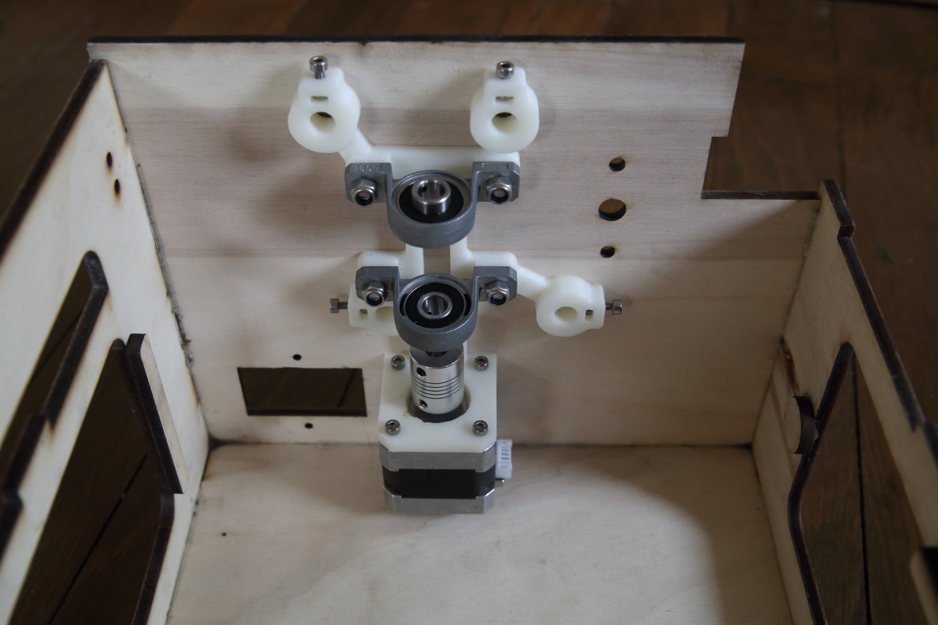
In order to perfectly align the KP08, you’ll use a 8mm rod before tighten the Nylstop screws.
Left support assembly
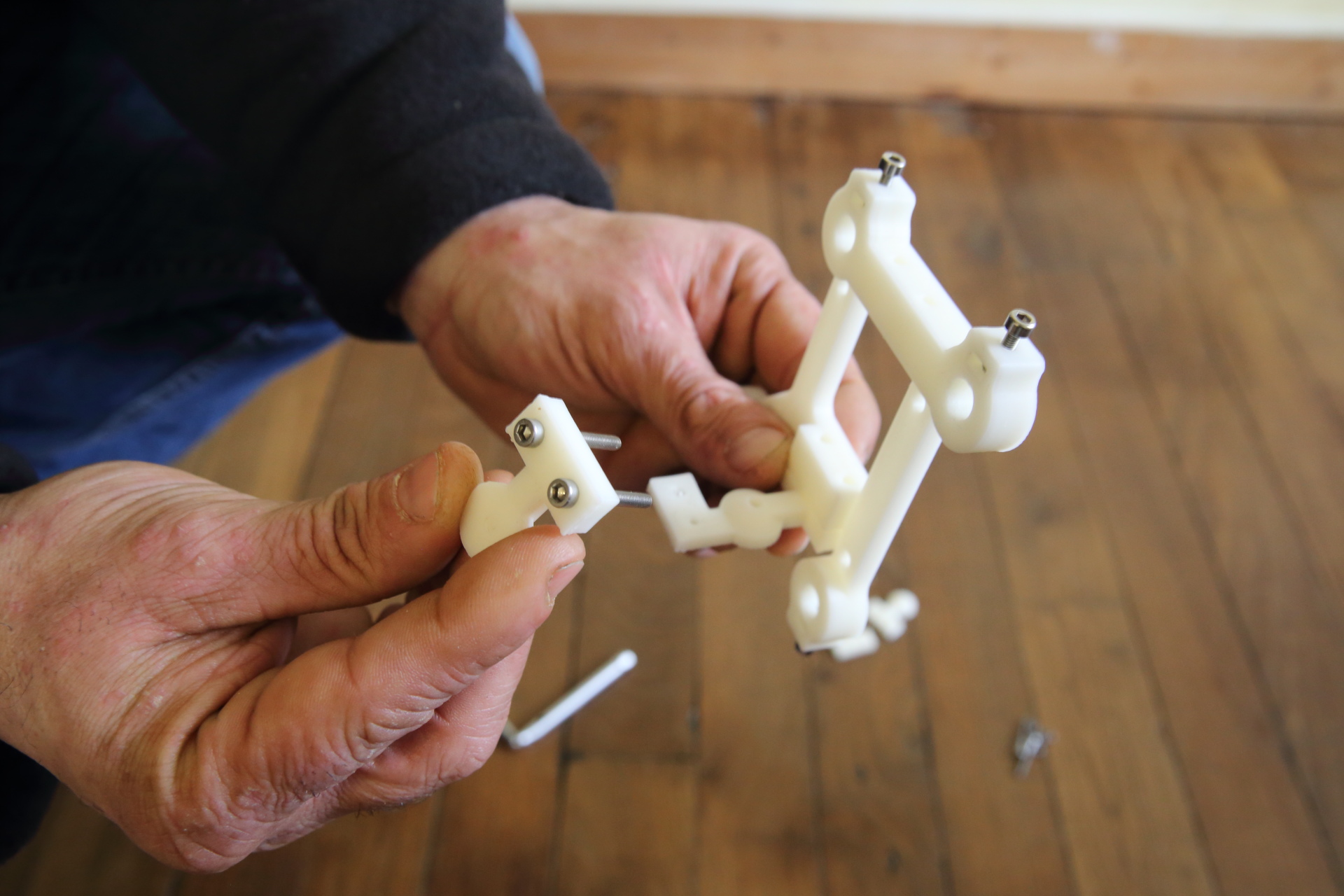
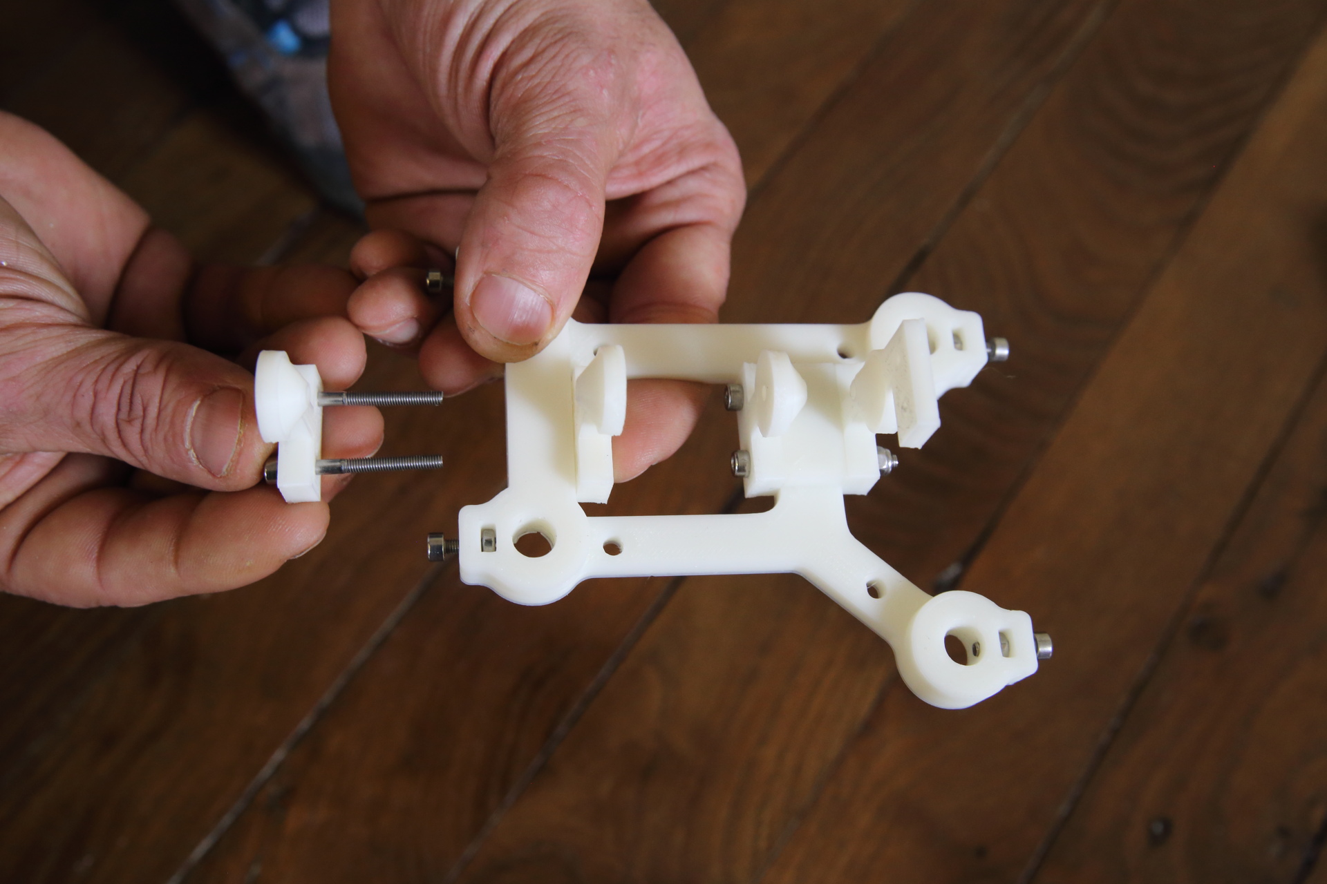
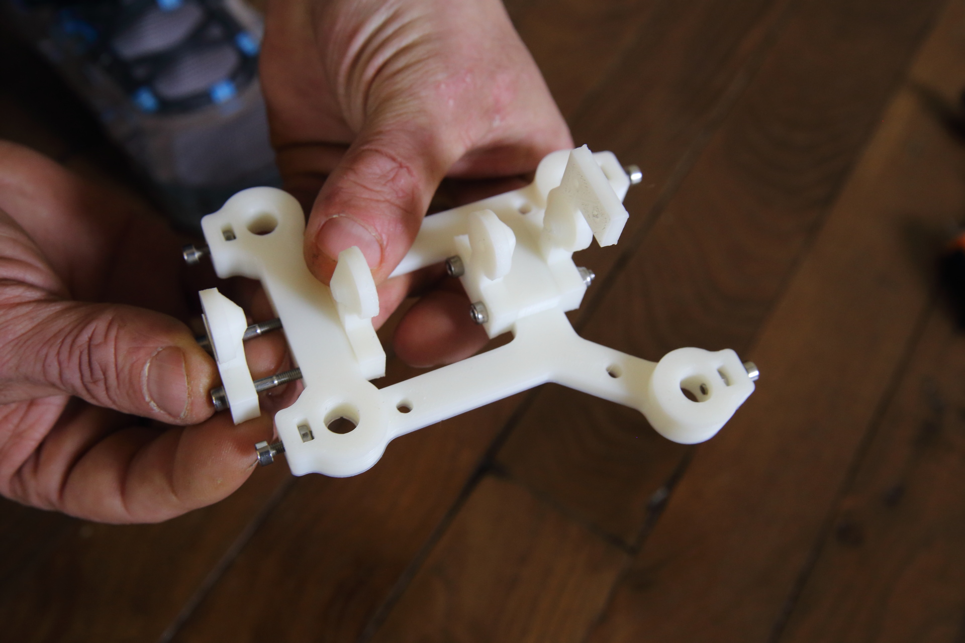
Position M3 bolts into the X axis” left support
Then you’ll place the M3x14mm BTR screws so that the nuts stay in place
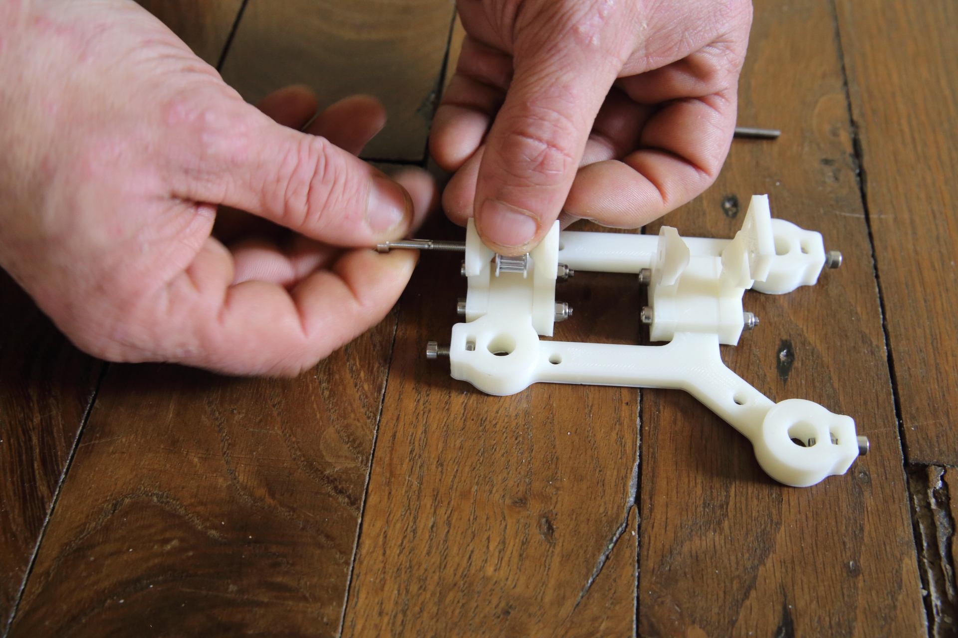
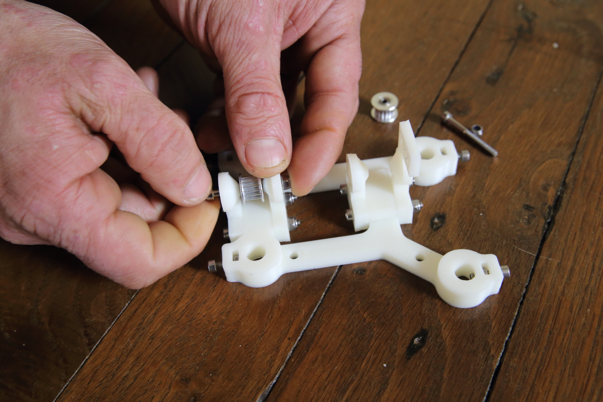
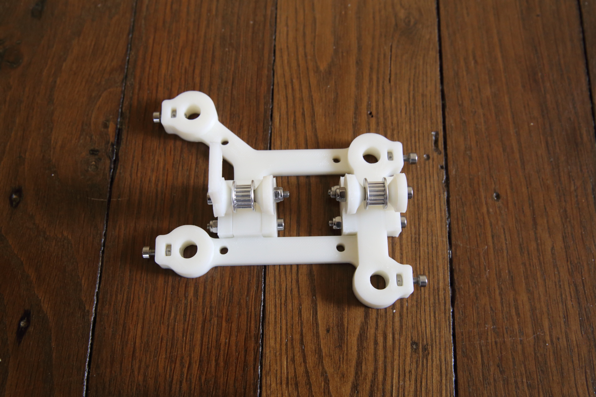
Pulley assembly
Add the pulleys on the left support
Locked these supports using 2 M3x30mm BTR and nylstop M3 bolts
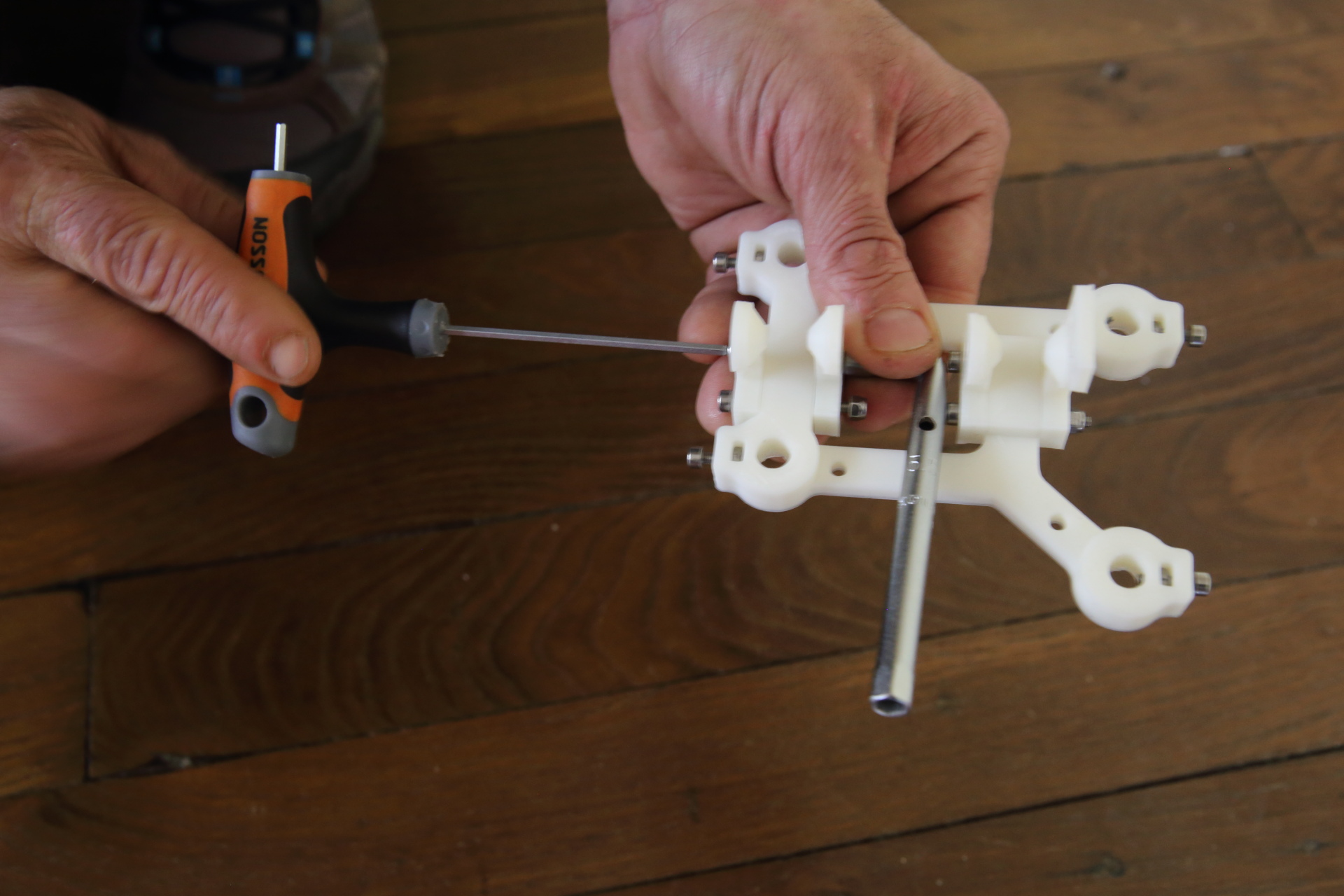
Be sure that pulley support allowing the endstop attachment is in right into the lower part
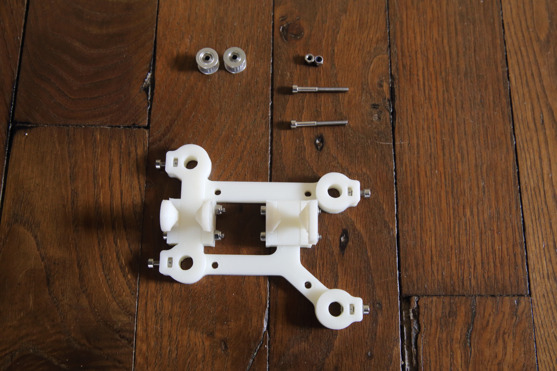
Install pulleys into dedicated supports
You should now obtain something similar to this photo
Installing the electro-magnet
TBA, magnet sourcing is changing
Preparing Y Axis
Assembling X Axis
…
Assembling Y Axis
- Put the 330 mm linear shaft beetween the left and right bottom support going throw the hole in the right side of the box. While positionning the linear shaft don’t forget to string 3 O-ring paper drive.
- Put the 400 mm linear shaft beetween the left and right top support going throw the hole in the right side of the box. While positionning the linear shaft don’t forget to string 3 sand paper paper drive.
Electronics & electric installation
- Installing MKS Gen1.4 Card
- Fixing Power supply
Software
Calibrating the printer
- paper placement
- Embosser calibration